xxllnc Expertsystemen: first steps
xxllnc Expertsystemen is the modelling environment where you will develop your own decision tree. In the Guided Tour tutorials we will refer to xxllnc Expertsystemen as Studio.
Tip: You can always press
[F1]to access help in the Desktop version. The Studio will open the right web page depending on which window is open. The web version does not support this feature.
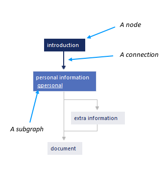
A model
All models consist of nodes connected to each other with connections, and graphs, which are groups of connected nodes. Models are made interactive with actions, such as questions and texts. All these elements together - graphs, nodes, connections and actions - form a decision tree model.
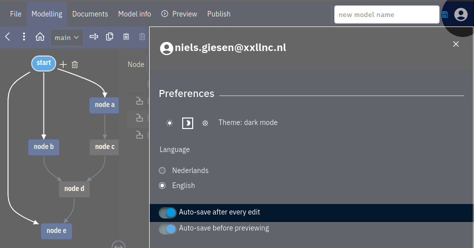
Studio Layout
The Studio is the modelling environment of xxllnc Expertsystemen. This is where you will develop your decision trees. After firing up the Studio you will see the following screen:
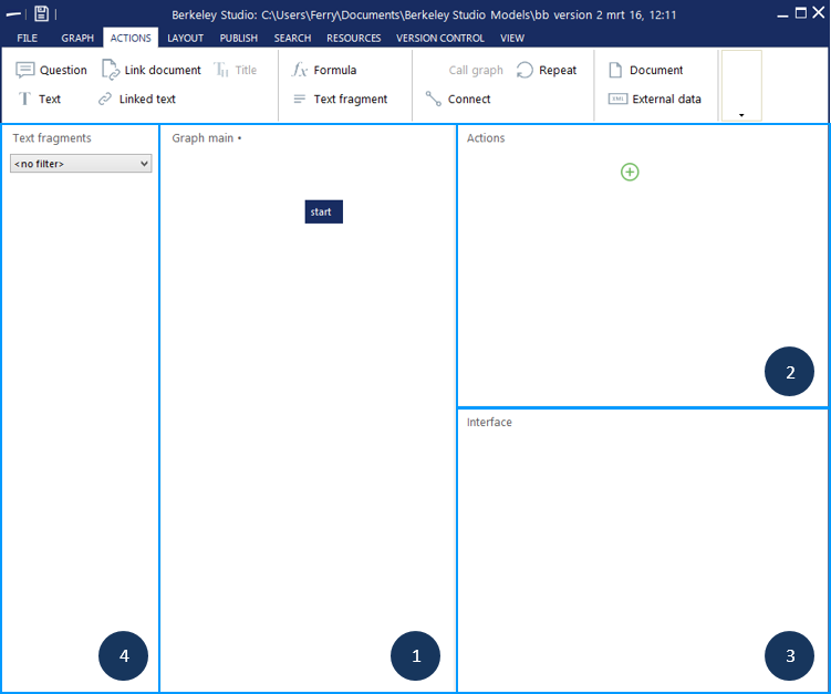
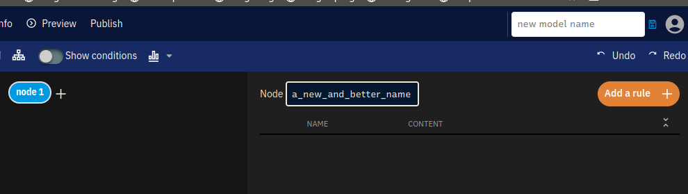
The Studio is divided into four panels and a menu. These are the sections that you will be using the most:
- Graph panel: the middle panel is where you will create and structure your model;
- Actions panel: this panel is where you view, add and edit actions of a node;
- Interface panel: this panel shows a small preview of your model;
- Text fragments panel: this panel shows all the text fragments that you have added to your model.
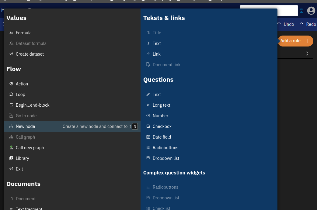
Via the top menu (the ribbon) you have access to all actions you can perform. Items are grouped by topic, such as Layout or Graph.
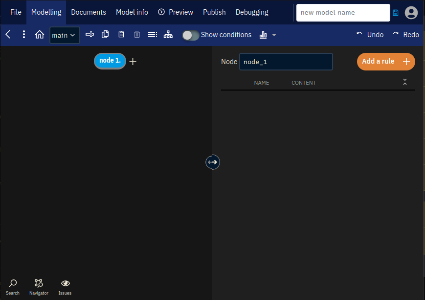
Nodes
From all the different items that you can add, nodes are the components that define the underlying structure of a decision tree model. Every node defines a new decision point in your graph.
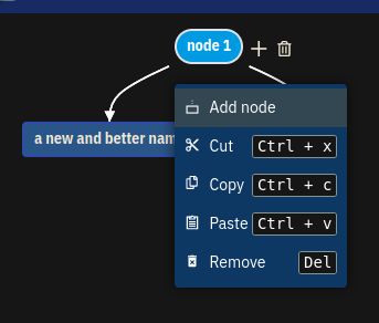
A new model will always have a node called start. To add another node, select the node ‘start’ and click ![]() New node in the Graph ribbon.
New node in the Graph ribbon.

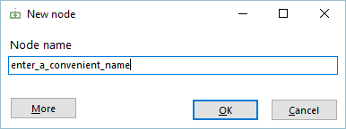
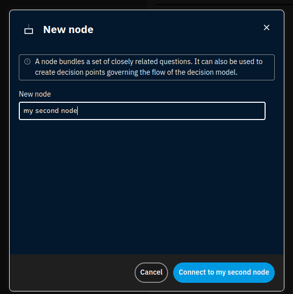
In the window that pops up, you can enter the node name. Be sure to give the node a name that covers what you want to place in that node.
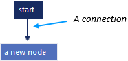
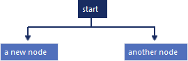
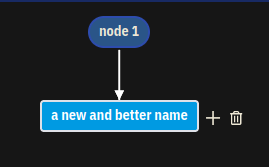
Adding a node also creates a connection (line) between the node you selected and the new one. It is also possible to connect multiple nodes to the same node. To do so, select the node ‘start’ again and add another node.
Connections
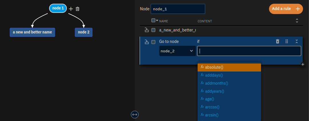
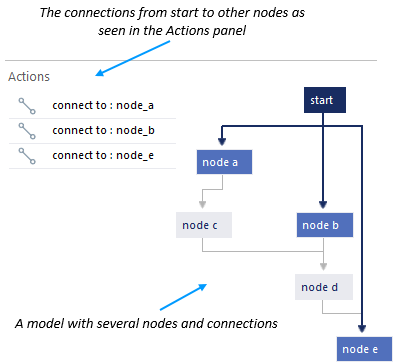
Connections show the flow of your model: they show all the possible paths through your decision tree. The path that a user follows depends on the decisions a user makes in the nodes. For example, answering a question with ‘yes’ may go through another path than answering it with ‘no’.
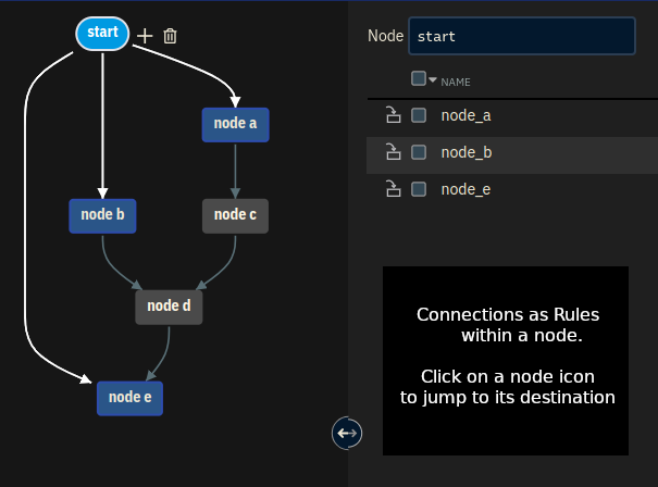
These connections are represented both by an arrow between nodes in the Graph panel and by an action in the Actions panel.
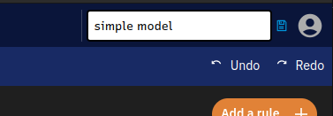
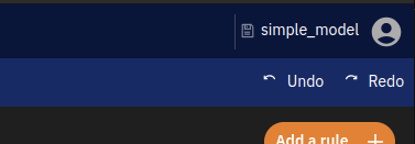
Saving your decision tree model
When working on a decision tree model, it is useful to save it often. You can do this by pressing [Ctrl+S] or by going to File in the top menu and clicking on ![]() Save.
Save.
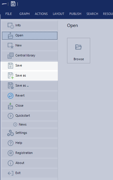
Save it in a convenient place where it’s easy to locate. It’s also good practice to create a separate folder for each model. For more about saving, see Saving and running your model